Fusion Imaging Significantly Reduces Contrast and Radiation Exposure During Standard EVAR
A B S T R A C T
Background: Standard endovascular aortic repair (EVAR) is frequently performed with few data regarding utilization of 2D-3D fusion imaging (FI).
Purpose: To evaluate a) feasibility and safety of 2D-3D FI to guide limb deployment during EVAR and b) efficacy of this technique compared to standard use of digital subtraction angiography (DSA) for guidance. Materials and Methods: Iliac limb deployment by guidance of 2D-3D FI (FUSION group, n=22 limbs) during EVAR was compared to (STANDARD group, n=23 limbs). Retrospectively, we analyzed feasibility (success-rate) and safety (patency of hypogastric artery; type Ib/III endoleak) of FI for limb deployment (FUSION group). Total contrast (ml) and median dose area product (mGy*cm2) per group to visualize the iliac bifurcation were compared.
Results: In the FUSION group, limb deployment was performed in 19/22 limbs (86.4%) and all hypogastric arteries were patent at the end of the procedure. Median volumes of contrast per bifurcation were 13.0 ml (RANGE 13–13ml) in the STANDARD and 2.2ml (RANGE 0–13ml) in the FUSION group (p=0.002); median dose area products per bifurcation were 11951mGy*cm2 and 2593.1mGy*cm2 (p=0.001), respectively.
Conclusion: Fusion imaging for guidance of limb deployment during standard EVAR is safe and feasible in the majority of procedures and can significantly reduce contrast volume and radiation exposure even if compared with optimal preparation by predicting optimal C-arm positions. Therefore, FI should be used whenever possible.
Keywords
Standard EVAR, fusion imaging, radiation reduction, contrast media reduction
Introduction
Since introduction of endovascular aortic repair (EVAR) it has evolved as the first-line therapy of infra-renal abdominal aortic aneurysms (AAA) for suitable anatomies [1]. Concerns that have been associated with EVAR are exposure to considerable doses of radiation and contrast agent. The latter has been identified as a risk factor for renal malfunction, especially in patients with pre-existing renal dysfunction and diabetes [2]. The incidence of acute kidney injury following standard EVAR has been reported in up to 18.8% of patients and therefore represents a common problem [3]. Radiation exposure on the other hand may put patients and interventionalists at risk [4, 5]. Acute radiation-induced DNA damage has been confirmed in operators performing EVAR cases [6]. Hence it seems important to reduce both radiation and contrast exposure during EVAR. In this context fusion imaging (FI) has been introduced recently to guide endovascular procedures. This technique produces a 3D vascular model which is derived from either MRA or CTA [7]. The model is overlaid intra-operatively with live fluoroscopy imaging after co-registration of pre-operative MRA or CTA images with anatomical landmarks on single-shot images acquired in two planes (2D- 3D registration) or cone-beam CT (3D-3D registration) [7, 8]. So far studies regarding the potential of FI to reduce contrast and radiation exposure have focused on endovascular thoracic aortic or complex (thoraco-) abdominal aortic repair [7-12]. Standard EVAR procedures however are performed more frequently than complex procedures and there are few data regarding utilization of FI during standard EVAR. We recently reported the implementation of calculating C-arm positions prior to standard EVAR procedures and found a significant reduction of contrast and radiation exposure [13]. In this context, as new FI techniques are emerging, we now evaluate the feasibility and safety of peri-interventional FI during standard EVAR procedures in combination with pre-interventional calculation of C-arm positions [14]. We hypothesize that contrast and radiation exposure can be further reduced in comparison to DSA guidance by use of pre-interventional CTA based calculation of C-arm positions alone.
Table 1: Patients’ anatomic and clinical data.
|
|
FUSION (study, n=12) [INTERQUARTILE RANGE] |
STANDARD (control, n=12) [INTERQUARTILE RANGE] |
|
Vascular anatomy |
|
|
|
Neck length (mm) |
30 [12-66] |
28 [25-38] |
|
Neck diameter (mm) |
20.5 [16-23] |
24 [21-27] |
|
Distal landing zone length (mm) |
48 [39-70] |
53 [32-83] |
|
Distal landing zone diameter (mm) |
12.5 [9-19] |
12 [10-14] |
|
Diameter AAA (mm) |
55.5 [50-63] |
51 [50-63] |
|
Vascular Access |
|
|
|
Percutaneous |
12 |
11 |
|
Femoral exposure |
0 |
1 |
|
Stent grafts |
|
|
|
Endurant IIs (Medtronic) |
8 |
6 |
|
InCraft (Cordis®) |
2 |
2 |
|
E-tegra (Jotec®) |
2 |
2 |
|
E-xtra Design (Jotec®) |
0 |
2 |
Materials and Methods
I Patient Selection, Study Design, Endpoints
Retrospectively, we identified 12 consecutive patients (10 men, 72.6+/- 7.8y) who had undergone standard EVAR (defined as infra-renal, bifurcated stent-grafting) after FI had been available in the interventional radiology department in 5/2017. Table 1 shows anatomic and procedural data. For the FUSION group, an attempt was made to solely deploy n=22 limbs using 3D FI with 2D registration for guidance (Figure 1).
The control group (STANDARD group) consisted of a historic collective of n=12 consecutive patients with n=23 limb deployments. In the STANDARD group C-arm angulations had been simulated prior to the EVAR in order to predict the optimal view onto the distal landing zone during the procedure. These pre-calculated angulations were used during a retrograde contrast injection with DSA in order to visualize the iliac bifurcation. This method of simulating the optimal C-arm has been published earlier [13]. In brief: a pre-operative CTA was analyzed using 3D post-processing software (Syngo.via, Version VA20B_HF06; Siemens Healthcare). Optimal C-arm positions were simulated, both in oblique as well as cranio-caudal positions, in order to visualize the distal landing zones at the iliac bifurcation. These C-arm angulations were used intra-operatively to visualize for digital subtraction angiographies (DSA) of the landing zones. Endpoints included feasibility (rate of successful limb deployments by FI guidance [%]), safety (patency of ipsilateral hypogastric iliac arteries on final DSA and post-operative CTA [%], rate of type Ib and type III endoleaks [%]), radiation (mGy*cm2), and contrast agent (ml) exposure for visualizing the distal landing zones in both groups. All patients have been treated within the instruction for use as specified for each device.
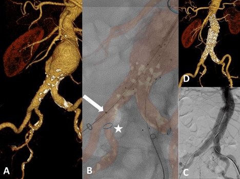
Figure 1: Fusion imaging guided deployment of bifurcated infrarenal aortic prosthesis. A) 3D reformation from a pre-procedural CTA. B) Fused image: deployment of the right limb by guidance of FI. Note the blue ring marker (white asterisk) indicating the ostium of the right hypogastric artery. The distal marker of the ipsilateral limb (white arrow) is visualized during FI-guided deployment. Moreover, the infra-renal and distal landing zones on the left limb have been flagged during planning of the procedure with ring markers. C) Final DSA confirms exclusion of the AAA and patent hypogastric arteries on both sides. D) 3D reformation derived from the post-procedural CTA three days later confirms accurate position of both limbs and a patent hypogastric artery on both sides.
II Fusion imaging for EVAR Guidance
For EVAR guidance in the FUSION group dedicated software (VesselNavigator®, Philips Healthcare, Best, Netherlands) on a stand- alone computer was used outside the angiography suite. After CTA data sets had been loaded from the picture archiving and communication system (PACS (IMPAX EE®, R20_XV, Agfa-Healthcare, Bonn, Germany)), three steps had to be performed for preparation. The first two steps are performed prior to the procedure, the third step is carried out with the patient on the angiography table. There are two ways of fusion technique. While the 3D-3D registration is performed by using an additional cone-beam CT (CBCT) acquired on the table, we used 2D-3D technique in our study. The following steps are necessary for preparation.
i Vessel Segmentation
Vessels are segmented semi-automatically on axial, coronal and/or sagittal thin sliced (1mm) CTA images. At the end of this step a 3D model of the vasculature is previewed.
ii Procedural Planning
During this step the orifice of vessels can be selected and flagged (markers are shown later the overlaid 3D model) and c-arm angulations can be preset.
iii Registration
This final step represents the actual fusion process and is performed with the patient on the table. It is important that the patient is not moved once this step has been completed. There are two ways of fusion technique. While the 3D-3D registration is performed by using an additional cone beam CT acquired on the table, in this study the 2D-3D technique was utilized for fusion. For this, two fluoroscopic images are produced in oblique positions (we aimed at 45° right and left oblique projections). These images are overlaid with the 3D vascular model and bone structures derived from the pre-operative CTA scan. In this study mainly pelvic segments or parts of the lumbar spine were used for this adjustment.
Once fluoroscopic and CT images have been merged one may proceed with live imaging and the endovascular procedure. The 3D vascular model with reference markers is shown on an additional screen side by side to the conventional fluoroscopy monitor.
III EVAR Procedure with Fusion Imaging
All EVAR procedures were electively planned and performed by the same interventional radiologist with 9 years of experience and a vascular surgeon with 12 years of experience (> 50 EVAR procedures per year) on an identical angio suite (Allura Xper 3.4; Philips Healthcare, Hamburg, Germany) under general anesthesia. A percutaneous bilateral femoral approach (ProGlide®, pre-close fashion) was used in all patients. After image registration, the main body of the stent graft was placed except one with femoral exposure; within the abdominal aorta, and a pigtail catheter was inserted above the renal arteries via the contralateral access. After locating the renal arteries and the aortic bifurcation on DSA, the main body was deployed below the lowest renal artery. Discrepancies between the orifices of the renal arteries on DSA and the FI 3D model were corrected manually by readjusting the fusion roadmap. In the majority of cases before FI-guided deployment of the limbs the correct position to the 3D model was confirmed by placing a ""RIM”-shaped catheter in the aortic bifurcation". The ipsilateral part of the main body was not deployed until the contralateral gate had been cannulated with a stiff guidewire in place. Then, deployment of the limbs by exclusively using FI was attempted. The FUSION group consisted of 12 patients (22 limbs). Two limbs were excluded (one patient with an iliac branch device on one side, one patient with failure of the FI screen after first limb deployment. If the mismatch between the 3D model on the fusion screen and the stiff guidewire (marking the vessel axis) was not acceptable, a conventional procedure was carried out to depict the landing zone. In these cases, pre-operatively calculated tube angles were applied to the C-arm with manual retrograde DSA using a 20 mL syringe (one third normal saline [0.9%], two thirds contrast medium) to identify the iliac bifurcation. Finally, a DSA using high-pressure injector was acquired before the procedure was terminated.
IV Data Collection
Usage of contrast media (ml) during each EVAR procedure, radiation dose (mGy*cm2) for each DSA run and the final dose area product were obtained from the digital report of procedure. Radiation dose and the amount of contrast medium per iliac bifurcation were compared between both groups. Written, informed consent was not applicable, as this was a retrospective study. Local ethic review committee approval was granted (17-274A).
V Statistical Analysis
The differences between the two groups were tested by using the non- parametric Mann Whitney U test. Statistical significance was set at p<.05. Statistical evaluation of the data was performed by using dedicated statistical software (SPSS 22 for Windows; IBM, Armonk, NY, USA).
Results
Fusion of the fluoroscopic images with the pre-procedural CTA using the 2D-3D registration fashion was possible in all procedures. Deployment of a limb exclusively by FI guidance was feasible in 19/22 attempts (86.4%). In three instances there was serious mismatch between the 3D vascular model and the course of the indwelling stiff guidewire so that a conventional DSA approach was necessary. In these failed attempts, evaluation of the corresponding pre-procedural CTA gave no hint on the underlying reason: the iliac axes in question showed mild to moderate kinking and calcification. With regard to safety all (100%) ipsilateral hypogastric arteries were patent at completion angiography as well as on the post-procedural CTA scan. No type Ib or III endoleaks were detected in both groups.
The median volumes of contrast media needed for limb deployment at the iliac bifurcation were 13.0 ml (RANGE 13–13ml) in the STANDARD group. In the FUSION group a median of 2.2ml (RANGE 0–13ml) of contrast medium were utilized to visualize and deploy the limb at the iliac bifurcation (p=0.002). The median dose area products per bifurcation were 11951mGy*cm2 in the STANDARD and 2593.1mGy*cm2 in the FUSION group (p=0.001).
Discussion
Our study results demonstrated feasibility and safety of FI during standard EVAR procedures to guide limb deployment. We observed a feasibility rate of 86.4%. Furthermore, we further showed that contrast media and radiation exposure is significantly reduced in comparison to pre- interventional CTA based calculation of C-arm positions alone. The reason why we used this technique for guidance of limb deployment only instead for the whole procedure was the fact, that the presented technique was new, and we had decided to start implementing it in a less sensitive vessel territory as compared to the renal level. Fusion imaging is a relatively new method for EVAR guidance. For complex EVAR and TEVAR cases studies have shown that FI, primarily 3D-3D, can reduce the amount of contrast media and radiation exposure to patients and staff [10, 12, 15, 16]. Our study showed that 2D-3D FI in standard EVAR also reduces contrast media and radiation. This is in line with the literature which has shown this effect for complex as well as standard EVAR procedures [9-12, 17].
In most FI studies, a CBCT was acquired in order to register in 3D-3D fashion. There is limited published data on 2D-3D FI registration for guidance of standard EVAR with feasibility rates of up to 95.5% [9, 11, 17-19]. In this study, the feasibility rate for registration was 100%. The main reason for unsuccessful FI-guidance in the presen0t study was a significant mismatch of the 3D fusion model "despite successful registration" and the stiff guidewire in place. In theory, elongation or heavy kinking of the iliac arteries might be responsible for this mismatch as especially stiff wires alter vessel anatomy. Retrospective analysis of the vascular anatomy in those patients in which FI-guided deployment was not feasible showed no excessive kinking. Furthermore, patient movement may have disturbed image registration causing FI inaccuracy even though all patients of our study were treated under general anesthesia [10]. A potential method to circumvent FI-mismatches could possibly be a 3D-3D registration with the stiff guidewire in place which, however, would require an additional CBCT with significant increases of total radiation [17]. Future research efforts focus on developing software that is able to anticipate interaction of guidewires and vessel [9].
For standard EVAR, the CBCT needed for 3D-3D registration accounts for up to 4% of the total dose area product [9]. Moreover, during acquisition of the CBCT the sterile field might be compromised as the C-arm circles around the patient [9]. In contrast, 2D-3D registration with an initial DSA makes up for only 0.6% of dose area product. This is of note as major concerns of EVAR comprise occupational contrast and radiation exposure besides durability and rates of re-intervention [6, 20, 21]. Although radiation exposure is higher with complex EVAR cases (f/bEVAR), radiation protection during standard EVAR is essential since this procedure is more frequent and DNA damage of operators performing complex and standard EVAR cases has been observed [5, 6]. Planning the procedure at an early stage, e.g. by predicting optimal C- arm positions, reduces radiation and contrast media exposure [13]. Compared to fluoroscopy mode, DSA runs contribute the majority of radiation exposure and should preferably be reduced to limit the dose area product [22].
Stangenberg et al. reported sixteen FI guided standard EVAR procedures using the VesselNavigator® software with 2D-3D registration [11]. A high-pressure DSA (contrast volume: 10ml, injection rate: 15ml/s) was performed prior to deployment of any stent graft piece in order to correlate with the fusion model. Therefore, one might speculate that identification of the renal arteries followed by deployment of the main body could also have been conventionally guided by this initial DSA and that only limb deployment was truly navigated by FI. From our experience the initial DSA to locate the proximal landing zone accounts for a relevant proportion (25-30%) of the overall dose area product. In order to reduce radiation exposure during this step of FI-EVAR- guidance one could alternatively selectively catheterize the lower of the two renal arteries and inject 5ml of contrast under fluoroscopy to confirm accurate registration. We were not able to calculate the share of registration in our study since the dose report does not show exposition for each fluoroscopy. But as the registration method presented does not require an initial DSA the share should be even less than 0.6%.
For obese patients significantly higher peak skin doses and dose area products have been reported during EVAR [23, 24]. In addition, fluoroscopic image quality might be compromised in obese patients, especially if oblique C-arm positions are required (which is typically the case in complex EVAR cases or for visualization of the distal landing zones during standard EVAR) and FI might offer advantages in this context, too [11]. Especially in these patients FI might support physicians in keeping the dose area product below recommended thresholds. Limitations are the retrospective and non-randomized design with relatively small sample size. Furthermore, investigator bias may have influenced results since a general awareness for radiation and contrast medium exposure has been reported to influence radiation and contrast dose [25]. In addition, some groups perform less precise fluoroscopy only, instead of DSA, to visualize the distal landing zones. In these cases, the relative effect of dose reduction by FI may be less pronounced.
In conclusion, the present study confirmed that FI using 2D-3D registration is feasible and safe. If used for guidance of limb deployment during standard EVAR contrast volume and radiation exposure can be significantly reduced even if compared with optimal preparation of the procedure by predicting optimal C-arm positions. Utilization of FI for guidance of EVAR should be used whenever possible. This is important as threshold values for standard EVAR have been decreased.
Conflicts of interest
None.
Funding
None.
Consent
Written, informed consent was not applicable, as this was a retrospective study. Local ethic review committee approval was granted (17-274A).
Article Info
Article Type
Research ArticlePublication history
Received: Thu 12, Sep 2019Accepted: Mon 14, Oct 2019
Published: Mon 30, Dec 2019
Copyright
© 2023 Susanne Anton. This is an open-access article distributed under the terms of the Creative Commons Attribution License, which permits unrestricted use, distribution, and reproduction in any medium, provided the original author and source are credited. Hosting by Science Repository.DOI: 10.31487/j.RDI.2019.04.02
Figures & Tables
Table 1: Patients’ anatomic and clinical data.
|
|
FUSION (study, n=12) [INTERQUARTILE RANGE] |
STANDARD (control, n=12) [INTERQUARTILE RANGE] |
|
Vascular anatomy |
|
|
|
Neck length (mm) |
30 [12-66] |
28 [25-38] |
|
Neck diameter (mm) |
20.5 [16-23] |
24 [21-27] |
|
Distal landing zone length (mm) |
48 [39-70] |
53 [32-83] |
|
Distal landing zone diameter (mm) |
12.5 [9-19] |
12 [10-14] |
|
Diameter AAA (mm) |
55.5 [50-63] |
51 [50-63] |
|
Vascular Access |
|
|
|
Percutaneous |
12 |
11 |
|
Femoral exposure |
0 |
1 |
|
Stent grafts |
|
|
|
Endurant IIs (Medtronic) |
8 |
6 |
|
InCraft (Cordis®) |
2 |
2 |
|
E-tegra (Jotec®) |
2 |
2 |
|
E-xtra Design (Jotec®) |
0 |
2 |
References
- Wanhainen A, Verzini F, Van Herzeele I (2019) Editor's Choice - European Society for Vascular Surgery (ESVS) 2019 Clinical Practice Guidelines on the Management of Abdominal Aorto-iliac Artery Aneurysms. Eur J Vasc Endovasc Surg 57: 8-93.
- Saratzis A, Nduwayo S, Sarafidis P, Sayers RD, Bown MJ (2016) Renal Function is the Main Predictor of Acute Kidney Injury after Endovascular Abdominal Aortic Aneurysm Repair. Ann Vasc Surg 31: 52-59. [Crossref]
- Saratzis A, Melas N, Mahmood A, Sarafidis P (2015) Incidence of Acute Kidney Injury (AKI) after Endovascular Abdominal Aortic Aneurysm Repair (EVAR) and Impact on Outcome. Eur J Vasc Endovasc Surg 49: 534-540. [Crossref]
- Monastiriotis S, Comito M, Labropoulos N (2015) Radiation exposure in endovascular repair of abdominal and thoracic aortic aneurysms. J Vasc Surg 62: 753-761. [Crossref]
- de Ruiter QMB, Jansen MM, Moll FL, Hazenberg CEVB, Kahya NN et al. (2018) Procedure and step-based analysis of the occupational radiation dose during endovascular aneurysm repair in the hybrid operating room. J Vasc Surg 67: 1881-1890. [Crossref]
- El-Sayed T, Patel AS, Cho JS, Kelly JA, Ludwinski FE et al. (2017) Radiation-Induced DNA Damage in Operators Performing Endovascular Aortic Repair. Circulation 136: 2406-2416. [Crossref]
- Schulz CJ, Schmitt M, Bockler D, Geisbüsch P (2016) Feasibility and accuracy of fusion imaging during thoracic endovascular aortic repair. J Vasc Surg 63: 314-322. [Crossref]
- Tacher V, Lin M, Desgranges P, Deux JF, Grünhagen T et al. (2013) Image guidance for endovascular repair of complex aortic aneurysms: comparison of two-dimensional and three-dimensional angiography and image fusion. J Vasc Interv Radiol 24: 1698-1706. [Crossref]
- Panuccio G, Torsello GF, Pfister M, Bisdas T, Bosiers MJ et al. (2016) Computer-aided endovascular aortic repair using fully automated two- and three-dimensional fusion imaging. J Vasc Surg 64: 1587-1594. [Crossref]
- Sailer AM, de Haan MW, Peppelenbosch AG, Jacobs MJ, Wildberger JE et al. (2014) CTA with fluoroscopy image fusion guidance in endovascular complex aortic aneurysm repair. Eur J Vasc Endovasc Surg 47: 349-356. [Crossref]
- Stangenberg L, Shuja F, Carelsen B, Elenbaas T, Wyers MC et al. (2015) A novel tool for three-dimensional roadmapping reduces radiation exposure and contrast agent dose in complex endovascular interventions. J Vasc Surg 62: 448-455. [Crossref]
- McNally MM, Scali ST, Feezor RJ, Neal D, Huber TS et al. (2015) Three-dimensional fusion computed tomography decreases radiation exposure, procedure time, and contrast use during fenestrated endovascular aortic repair. J Vasc Surg 61: 309-316. [Crossref]
- Blinded for Review.
- Kakkos SK, Tsolakis IA (2017) Commentary on "Pre-operative Simulation of the Appropriate C-Arm Position Using Computed Tomography Post-Processing Software Reduces Radiation and Contrast Medium Exposure During EVAR Procedures". Eur J Vasc Endovasc Surg 53: 275. [Crossref]
- Dijkstra ML, Eagleton MJ, Greenberg RK, Mastracci T, Hernandez A (2011) Intraoperative C-arm cone-beam computed tomography in fenestrated/branched aortic endografting. J Vasc Surg 53: 583-590. [Crossref]
- Dias NV, Billberg H, Sonesson B, Törnqvist P, Resch T et al. (2016) The effects of combining fusion imaging, low-frequency pulsed fluoroscopy, and low-concentration contrast agent during endovascular aneurysm repair. J Vasc Surg 63: 1147-1155. [Crossref]
- Hertault A, Maurel B, Sobocinski J, Martin Gonzalez T, Le Roux M et al. (2014) Impact of hybrid rooms with image fusion on radiation exposure during endovascular aortic repair. Eur J Vasc Endovasc Surg 48: 382-390. [Crossref]
- Jones DW, Stangenberg L, Swerdlow NJ, Alef M, Lo R et al. (2018) Image Fusion and 3-Dimensional Roadmapping in Endovascular Surgery. Ann Vasc Surg 52: 302-311. [Crossref]
- Kaladji A, Villena A, Pascot R, Lalys F, Daoudal A et al. (2019) Fusion Imaging for EVAR with Mobile C-arm. Ann Vasc Surg 55: 166-174. [Crossref]
- Nyheim T, Staxrud LE, Jorgensen JJ, Jensen K, Olerud HM et al. (2017) Radiation exposure in patients treated with endovascular aneurysm repair: what is the risk of cancer, and can we justify treating younger patients? Acta Radiol 58: 323-330. [Crossref]
- Sailer AM, Nelemans PJ, van Berlo C, Yazar O, de Haan MW et al. (2016) Endovascular treatment of complex aortic aneurysms: prevalence of acute kidney injury and effect on long-term renal function. Eur Radiol 26: 1613-1619. [Crossref]
- Maurel B, Hertault A, Sobocinski J, Le Roux M, Gonzalez TM et al. (2014) Techniques to reduce radiation and contrast volume during EVAR. J Cardiovasc Surg (Torino) 55: 123-131. [Crossref]
- Weiss DJ, Pipinos, II, Longo GM, Lynch TG, Rutar FJ et al. (2008) Direct and indirect measurement of patient radiation exposure during endovascular aortic aneurysm repair. Ann Vasc Surg 22: 723-729. [Crossref]
- Majewska N, Stanisic MG, Blaszak MA, Juszkat R, Frankiewicz M et al. (2011) Clinical factors increasing radiation doses to patients undergoing long-lasting procedures: abdominal stent-graft implantation. Med Sci Monit 17: MT97-MT103. [Crossref]
- Stansfield T, Parker R, Masson N, Lewis D (2016) The Endovascular Preprocedural Run Through and Brief: A Simple Intervention to Reduce Radiation Dose and Contrast Load in Endovascular Aneurysm Repair. Vasc Endovascular Surg 50: 241-246. [Crossref]